Coating Failure Analysis with SEM-EDS for Aerospace Materials Development
A case study of how SEM-EDS was used for failure analysis of protective coatings, for materials development in aerospace engineering.
This technique can be used for failure analysis in a variety of industries; this example features a thermal barrier coating from a turbojet engine. This type of coating is used in various fields of engineering and must be able to withstand extremely high temperatures.
Materials Development in Aerospace Engineering
In aerospace engineering, engine materials need temperature and oxidation resistance, high strength, stiffness and fracture toughness. Factors such as efficiency and cost must also be considered. These challenging requirements create demand for new manufacturing techniques, and research into new alloys and surface coatings.
Example: Fragment from a Turbojet Engine
This example involves the microstructural and chemical characterisation of a thermal barrier coating, using SEM and EDS with the Thermo Scientific Axia ChemiSEM.
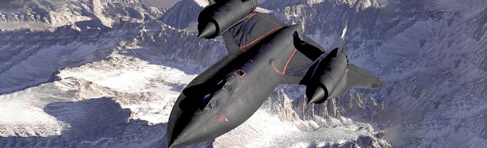
A fragment of afterburner liner from the engine of a Lockheed SR-71 aircraft was analysed. This is a high speed, high altitude aircraft manufactured in the late 1950s. The study focuses on the end-of-life, thermally fatigued thermal barrier coating from the afterburner liner of the turbojet engine. The aircraft had 15,000 flight hours, so the component is a good example of a heavily cycled material that’s been exposed to extreme stress.
Thermal Barrier Coatings
Thermal barrier coatings are currently used in various fields of engineering. New materials and deposition techniques are constantly being developed to improve their lifetime and durability. These types of coatings have complex structures and must operate in extreme high temperature environments – up to 1700°C in the case of the jet engine afterburner in this example.
SEM/EDS Analysis
The study reveals heavily evolved micro-structures. High temperature creep caused the diffusion of various elements and changes in the original structure. This lead to the decomposition of the thermally grown oxide layer and modification of the bond coat and top coat layers into a mix of oxides and phases.
Voids and cracks were located using large area imaging, alongside elemental information from EDS for characterising the various materials. The Axia ChemiSEM’s integrated, always-on EDS system brings microstructural and chemical information together, making the process much faster and more efficient.
Large Area Characterisation
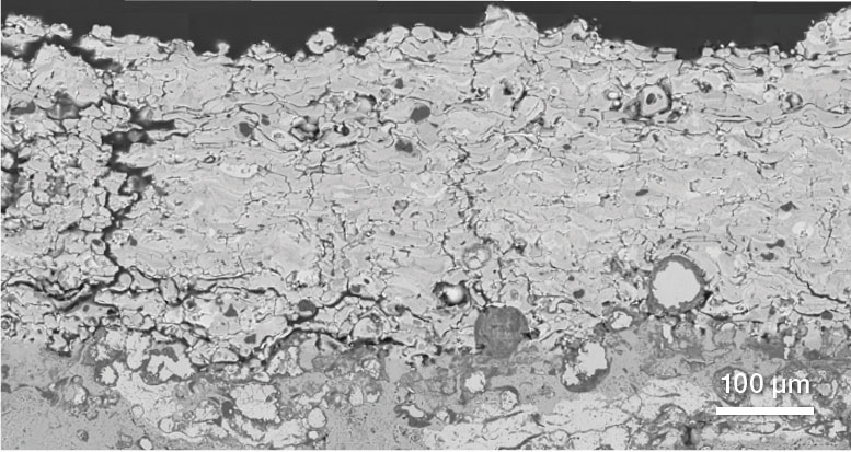
First, an overview of the fragment was acquired, showing the various layers. The Axia ChemiSEM’s image montage functionality generates a large-scale image by automatically tiling images. This takes around 30 minutes, including simultaneous EDS.
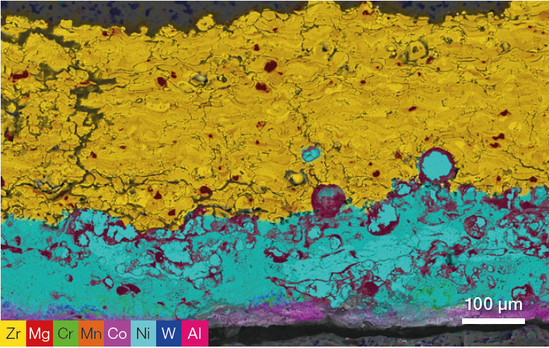
The greyscale image from the backscattered electron detector does not show the variability of materials through the different layers. However, when colour compositional information from EDS is added, you can instantly see the laters and the image becomes much clearer and easier to interpret:
Always-on EDS
Colour compositional information from EDS is available at any time with the Axia ChemiSEM. It’s collected continuously during imaging, and can be viewed live at any time at the press of a button.
Superalloy Substrate
Areas of interest were identified from the initial large area map for further analysis. These were examined closer at higher magnification.
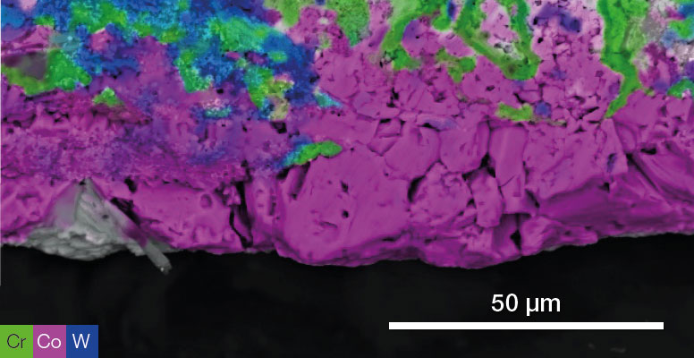
As well as combined compositional maps, individual elements can be shown or hidden, to view their distribution and locate abnormalities or areas of abundance.
In this example, the maps for Cr, Co and W highlight a clear inter-diffusion between the base superalloy and the bond coat. The image shows how Cr and W have migrated into the bond coat. This is common in thermal fatigue, when thermal cycles cause phase transformations, allowing components from the base metal to diffuse into the upper layer.
Identifying Causes of Failure
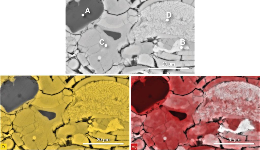
High magnification characterisation of the upper layer made several cracks visible. Cracks are one of the main causes of failure of thermal barrier coatings after thermal, causing delamination of the ceramic top coat.
The Zr and Mg images exhibit a different distribution of both elements, which suggests the presence of different phases even within a single layer.
Point analyses were taken from the various phases for further investigation, showing the percentages of various elements at each point.
Application Note
Full details of this study, with further results including more images, results and examples of line scans, are in a pdf application note.
If you’d like a copy, please contact us on +44 (0)1223 422 269 or info@blue-scientific.com.
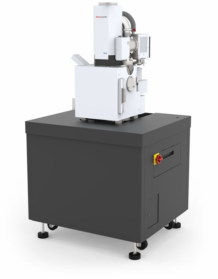
Thermo Scientific Axia ChemiSEM
The instrument used for this study is the Thermo Scientific Axia ChemiSEM, a new, entry level SEM system:
- Easy to use, entry-level SEM.
- Continuous, always-on EDS elemental analysis.
- Twice as fast as alternative SEM-EDS workflows.
- No air table required.
- Full service and support available from PhD level, factory-trained engineers.
More Information
Blue Scientific is the official distributor of Thermo Scientific entry-level SEM in the Nordic region. We’re available to answer all your questions – just get in touch: